Crank and Slotted Lever Mechanism: A Comprehensive Guide to Its Design and Applications
Introduction
The crank and slotted lever mechanism, an ingenious mechanical linkage, plays a crucial role in converting rotary motion into linear or reciprocating motion, finding widespread use in various industrial and automation applications. This comprehensive guide aims to provide a thorough understanding of the crank and slotted lever mechanism, covering its design, working principle, applications, and optimization strategies.
Working Principle
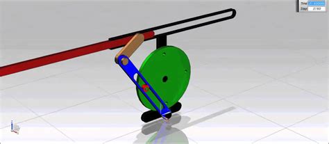
The crank and slotted lever mechanism comprises two primary components:
-
Crank: A rotating wheel or disk with a fixed pivot point, which provides the rotary input motion.
-
Slotted Lever: A pivoted arm or link with an elongated slot, which connects to the crank and guides its motion.
As the crank rotates, the slotted lever translates and reciprocates along the slot's length. The specific motion and direction of the slotted lever depend on the relative positions of the crank and slotted lever, as well as the geometry of the slot.
Design Considerations
Designing an effective crank and slotted lever mechanism involves careful consideration of several key factors:
-
Crank Radius: The length of the crank arm, which determines the magnitude of the linear motion in the slotted lever.
-
Slot Length: The length of the slot in the slotted lever, which limits the range of motion of the lever.
-
Slot Angle: The angle of the slot relative to the crank arm, which influences the direction of the lever's motion.
-
Materials: The choice of materials for the crank and slotted lever, which must withstand wear, stress, and environmental conditions.
Applications
The crank and slotted lever mechanism finds extensive applications across diverse industries, including:
-
Automotive: Engine valve actuation, steering systems
-
Industrial Machinery: Conveyor systems, packaging machines
-
Robotics: Linear actuators, robotic arms
-
Medical Devices: Surgical tools, patient positioning systems
-
Aerospace: Flight control systems, landing gear actuation
Optimization Strategies
To optimize the performance of a crank and slotted lever mechanism, consider the following strategies:

-
Motion Analysis: Analyze the motion of the mechanism to identify potential areas for improvement in speed, accuracy, and efficiency.
-
Materials Optimization: Select materials with optimal properties for the intended application, considering factors such as strength, wear resistance, and corrosion resistance.
-
Friction Reduction: Employ techniques to minimize friction, such as using lubricants, bearings, and reducing contact surfaces.
-
Balancing: Ensure the mechanism is balanced to avoid excessive vibrations and noise.
Common Mistakes to Avoid
To avoid common pitfalls in designing and using crank and slotted lever mechanisms, heed these mistakes:
-
Incorrect Slot Geometry: Errors in the slot length or angle can lead to unintended motion or premature failure.
-
Overstressed Components: Failing to account for load and stress distribution can result in component failure and reduced lifespan.
-
Insufficient Lubrication: Neglecting lubrication can lead to friction, wear, and energy loss.
-
Poor Balancing: An unbalanced mechanism can cause excessive vibrations and noise, reducing its efficiency and lifespan.
Step-by-Step Approach to Design
For successful design and implementation of a crank and slotted lever mechanism, follow these steps:
-
Define Requirements: Determine the desired motion, speed, and load capacity of the mechanism.
-
Select Crank and Slotted Lever: Choose the appropriate crank radius and slotted lever geometry based on the motion requirements.
-
Analyze Motion: Conduct motion analysis to verify the accuracy and performance of the mechanism.
-
Optimize Design: Employ optimization strategies to improve efficiency, durability, and cost-effectiveness.
-
Test and Validate: Thoroughly test the mechanism to ensure it meets design specifications and performs as intended.
Pros and Cons
Pros:

- Converts rotary motion into linear or reciprocating motion effectively.
- Simple and reliable design, easy to maintain and repair.
- Versatile, applicable in a wide range of industries and applications.
- Relatively low cost compared to other linear motion mechanisms.
Cons:
- Can be less accurate than other linear motion mechanisms, especially at high speeds.
- May introduce noise and vibrations if not properly balanced.
- Requires regular lubrication to prevent friction and wear.
Comparative Table
| Feature |
Crank and Slotted Lever Mechanism |
Other Linear Motion Mechanisms |
| Motion Type |
Rotary to Linear/Reciprocating |
Linear |
| Complexity |
Simple |
Complex |
| Accuracy |
Moderate |
High |
| Cost |
Low |
Moderate to High |
| Durability |
Good |
Varies |
| Applications |
Diverse |
Specific |
Data and Statistics
- According to a study by the American Society of Mechanical Engineers (ASME), crank and slotted lever mechanisms account for over 50% of all linear motion mechanisms used in industrial applications.
- The global linear motion market is projected to reach $32.5 billion by 2027, driven in part by the growing demand for automation and robotics.
- In the automotive industry, crank and slotted lever mechanisms are used in approximately 75% of all engine valve actuation systems.
Conclusion
The crank and slotted lever mechanism remains a versatile and cost-effective solution for converting rotary motion into linear or reciprocating motion. By understanding its design principles, applications, and optimization techniques, engineers can create efficient and reliable mechanisms that meet the diverse needs of modern industries. As technology continues to advance, the crank and slotted lever mechanism will continue to play a vital role in driving innovation and automation.
